
Integrated Ball Spline Assemblies
Integrated Ball Spline Assemblies: drawing-based evaluation of spline geometry, mating interfaces and the complete assembly.
Structure & Application Boundaries
Integrated Ball Spline Assemblies: drawing-based evaluation of spline geometry, mating interfaces and the complete assembly.
Selection Inputs
Complete drawing, mating-part interfaces, quantity, load direction, torque, travel, duty cycle, accuracy and environment.
Product & Configuration
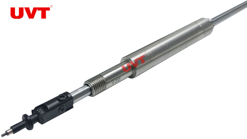
Reference product photo. Files apply only to their named configurations.
Drawing & Assembly Requirements
- Drawing number & revision
- Defined in the approved drawing specification
- Base spline / mating interfaces
- Defined in the approved drawing specification
- Custom geometry & shaft ends
- Defined in the approved drawing specification
- Material & lubricant
- Defined in the approved drawing specification
- Operating load & duty cycle
- Defined in the approved drawing specification
- Inspection & acceptance conditions
- Defined in the approved drawing specification
Selection Guides & CAD Requests
Guides are general reference PDFs. Request 2D / 3D CAD for your exact configuration.
Assembly & Revision
Drawing number, revision, base series, custom dimensions, interfaces and inspection requirements: defined in the approved quotation and drawing.
Interfaces & Commissioning
Verify housing or flange dimensions, axial retention and alignment using the exact drawing. Avoid removing the nut without a dummy shaft; confirm lubricant and interval for the application.
Special materials, cleanroom, vacuum and dry-running suitability require individual review.
Related Equipment
- Replacement of discontinued parts
- OEM machine builders
- Special equipment